IMAGES TAKEN NEAR TO
Markfield Road, LONDON, N15 4RB
Introduction
This page details the photographs taken nearby to Markfield Road, N15 4RB by members of the Geograph project.
The Geograph project started in 2005 with the aim of publishing, organising and preserving representative images for every square kilometre of Great Britain, Ireland and the Isle of Man.

There are currently over 7.5m images from over14,400 individuals and you can help contribute to the project by visiting https://www.geograph.org.uk
Image Map
Images are licensed for reuse under creativecommons.org/licenses/by-sa/2.0
Notes
- Clicking on the map will re-center to the selected point.
- The higher the marker number, the further away the image location is from the centre of the postcode.
Image Listing (139 Images Found)
Images are licensed for reuse under creativecommons.org/licenses/by-sa/2.0
Image
Details
Distance
1

Markfield Road Pumping Station, South Tottenham, London N15
Grade II listed pumping station building described http://list.english-heritage.org.uk/resultsingle.aspx?uid=1358862
Image: © Jim Osley
Taken: 17 Jun 2010
0.00 miles
2

Bull sculpture, Markfield Park
Unveiled in July 2011, the steel sculpture is the work of Jack Gardner. http://www.tottenhamjournal.co.uk/news/picasso_style_steel_bull_unveiled_in_tottenham_s_markfield_park_1_976904. In the background, the Markfield Pumping Station.
Image: © Jim Osley
Taken: 18 Jul 2014
0.00 miles
3
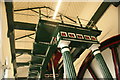
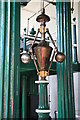
Looking up at the Markfield Beam Engine #5
Looking north-northwest.
Image: © Robert Lamb
Taken: 18 Sep 2016
0.00 miles
4

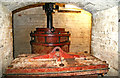
View of a collection of chamber pots in the Markfield Beam Engine room
Looking north-northeast.
Image: © Robert Lamb
Taken: 18 Sep 2016
0.00 miles
5
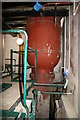
Markfield Beam Engine & Museum - air vessel
In the basement under the beam pumping engine is this air vessel on the pumping main. Reciprocating pumps need a 'shock absorber' to prevent the pressure of pumping from fracturing the pipes, especially unpleasant with a sewage pump. The air vessel has liquid at the bottom and compressed air at the top. The air is compressible and acts like a spring to store energy while the pump delivers and return it on the suction stroke, thus smoothing the flow in the pipes.
Image: © Chris Allen
Taken: 24 Jul 2011
0.00 miles
6
Markfield Beam Engine & Museum - the beam
This is the wrought iron riveted box girder beam of this 1886 Woolf compound beam engine by Wood Brothers of Sowerby Bridge. This is at the 'crank end' with the connecting rod closest to the camera and one of the sewage pump connected to the next boss on the beam. The engine is now fully restored and can be run on steam several times a year. That this was achieved over many years was a testament to the small group battling to save the site
Image: © Chris Allen
Taken: 21 Jun 2009
0.00 miles
7
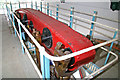
Markfield Beam Engine and Museum - sewage pump
Markfield Road Pumping Station has an 8 column Woolf compound rotative beam pumping engine. This drives two single acting plunger pumps for pumping the sewage. The pumps are 26" bore by 51" stroke and could each move 2 million gallons per day. One pump is operated from the crank half of the beam by two rods passing either side of the crank's arc of rotation, the other pump is driven from the high pressure cylinder's piston tail rod. This is the pump at the crank end of the engine. Having pumps either side of the beam's transverse centreline makes for a smoother delivery as when one pump is on the suction stroke the other is on the discharge stroke. On an earlier visit I had photographed the other pump but had missed this one out.
Image: © Chris Allen
Taken: 24 Jul 2011
0.00 miles
8
Markfield Beam Engine and Museum - the governor
The engine is an 8 column Woolf compound rotative beam pumping engine built in 1886 by Wood Bros of Sowerby Bridge. This shows the governor. It is a centre weighted or Porter type governor driven by a shaft and gearing from the crankshaft. It operates a throttle valve upstream of the high pressure valve chest. On a pumping engine like this that runs at constant load its real purpose is to act as an overspeed governor rather than a speed regulator. The speed is adjusted to the load by manually adjusting the high pressure cut-off. If load was to be lost the engine would speed up and the governor would hopefully act to stop a dangerous increase in speed.
Image: © Chris Allen
Taken: 24 Jul 2011
0.00 miles
9
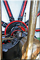
Markfield Beam Engine and Museum - crankshaft and flywheel
This is an 1886 built 8 column Woolf compound beam engine. This is a view on the crank and flywheel. The latter is 27' (some sources say 28') diameter and weighs about 17 tons. It is built up with 10 spokes. Immediately in front of the boss are the two eccentrics to drive the piston valves. Then there are two sets of unequal bevel gears - one for the high pressure expansion gear and the other for the governor drive. On the extreme left are the two rods driving one of the sewage pumps.
Image: © Chris Allen
Taken: 24 Jul 2011
0.00 miles
10

Markfield Road Pumping Station
Home to a beam pumping engine that should have been in steam but wasn't due to boiler problems. There was all sorts of other family fun going on around the site.
Image: © Chris Allen
Taken: 24 Jul 2011
0.00 miles