
IMAGES TAKEN NEAR TO
Chesterfield Road, LICHFIELD, WS13 6QW
Introduction
This page details the photographs taken nearby to Chesterfield Road, WS13 6QW by members of the Geograph project.
The Geograph project started in 2005 with the aim of publishing, organising and preserving representative images for every square kilometre of Great Britain, Ireland and the Isle of Man.

There are currently over 7.5m images from over14,400 individuals and you can help contribute to the project by visiting https://www.geograph.org.uk
Image Map
Images are licensed for reuse under creativecommons.org/licenses/by-sa/2.0
Notes
- Clicking on the map will re-center to the selected point.
- The higher the marker number, the further away the image location is from the centre of the postcode.
Image Listing (41 Images Found)
Images are licensed for reuse under creativecommons.org/licenses/by-sa/2.0
Image
Details
Distance
1
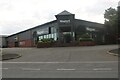
Magnet Kitchens on Birmingham Road, Lichfield
Image: © David Howard
Taken: 19 Jun 2022
0.08 miles
2
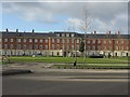
Lichfield - striking building by the Birmingham Road roundabout
Image: © Peter Whatley
Taken: 7 Dec 2011
0.08 miles
3
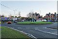
Roundabout on the western side of Lichfield
The western ring road is meeting Birmingham Road.
Image: © Bill Boaden
Taken: 27 Dec 2017
0.09 miles
4
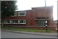
Shire House offices on Birmingham Road, Lichfield
Image: © David Howard
Taken: 19 Jun 2022
0.11 miles
5
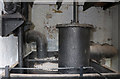
Sandfields Pumping Station - condensing plant
The surviving brick engine house contains a Cornish beam pumping engine built in 1873. This is the upper part of the condensing plant that sits in a big iron tank that was filled with canal water that was being constantly returned to the canal by a pump on the other side of the wall to the left. The big pipe in the left background is the eduction (exhaust) pipe bringing spent steam from the cylinder into the top of the surface condenser that is bottom and slightly left of centre. The condensate and incondensable gases are removed from the condenser by the air pump in the foreground that is operated by a rod from the beam. Top left is the boiler feed pump that takes warm condensate from the hotwell and returns it to the boiler.
So far, so good! But, the air pump has a large bore pipe to the right that returned to the canal and according to the original drawing it has been extended upward above the level of the hot well to accommodate this pipe. This has led to a very lively discussion both on site and via e-mail. A surface condenser only contains a volume of water corresponding to the steam used by the engine and all this should return to the boiler via the feed pump. As such, it needs a relatively modestly sized air pump and no need to return large volumes to the canal. On the other hand, a jet condenser needs (say) 20 times the weight of steam in injection water and would have a large excess to return to the canal. Furthermore part of the original specification refers to a surface condenser that could be converted to injection if found necessary.
Therefore, our best guess is that this is arranged primarily as a surface condenser but could have an element of injection (jet) condensing if needed and that the air pump is therefore oversized relative to that required for pure surface condensing and has an overflow to return excess water to the canal.
However, that is an element of conjecture based on available evidence.
You may wake up now!
Image: © Chris Allen
Taken: 28 Feb 2020
0.12 miles
6
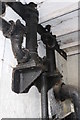
Sandfields Pumping Station - Auxiliary Pumps
Two pumps on the main pump side of the beam centre and mounted below the driving floor level. The closest is the boiler feed pump and draws from the hot well incorporated in the air pump. The further one was disused and supplied compressed air to the air vessel on the discharge main. Its role had been superseded by a separate steam driven Westinghouse compressor. The big pipe bottom right is the eduction pipe taking exhaust steam to the condenser.
Image: © Chris Allen
Taken: 28 Feb 2020
0.12 miles
7
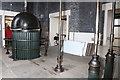
Sandfields Pumping Station - pump rods
This Cornish beam engine was the fourth engine on site and built in an 1873 extension. It came out of service in 1924 but remains preserved, currently by the Lichfield Waterworks Trust that is in the building with the permission of Persimmon Homes. This shows the pump rods on the 'outdoor' half of the beam. The rod closest to the camera on the right operated a pump for charging the air vessel with compressed air. This became disused c1905 when it was replaced with a Westinghouse compressor. The rod to its right near the right hand edge operated the boiler feed pump that took condensate from the air-pump's hot-well. In the centre is the air-pump operating rod. On the left is the main pump that incorporates a fluted balance weight box between the pump rod and the pump plunger below. This weight provided the power to pump the water against a head of 355' at a rate of 2 million gallons/day. The Trust has confirmed that the weights had previously been removed from the fluted weight box and that it is now empty.
Image: © Chris Allen
Taken: 28 Feb 2020
0.12 miles
8
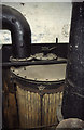
Sandfields Pumping Station - surface condenser
This is relatively unusual for a Cornish beam pumping engine. A vertically orientated surface condenser with the steam in the tubes and canal water surrounding them in a cast iron tank. Modern power station surface condensers have the steam outside the tubes and circulating cooling water in the tubes. I suspect the surface condenser was used, rather than a jet, due to the canal water being possibly of dubious quality. The bell mouth to bottom right is the condenser tank overflow and feeds the water to a circulating pump that returns it to the canal, warmer than when it arrived. See also Image and Image
Image: © Chris Allen
Taken: 4 Nov 2001
0.12 miles
9
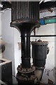
Sandfields Pumping Station - the pump
The business end of the 1873 built Cornish beam pumping engine. This shows the top of the bucket and plunger pump force pump and the bottom of its fluted balance weight box. The well pump is below and connected to this and its bucket is 25.75" diameter. The plunger of the force pump is seen here and is 17 13/16" diameter. The delivery is 200.9 gallons/double stroke.
Image: © Chris Allen
Taken: 28 Feb 2020
0.13 miles
10
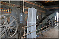
Sandfields Pumping Station - Cornish beam engine
The waterworks closed some years ago and the building is now the property of Persimmon Homes but the Lichfield Waterworks Trust has access to the buildings and is restoring the 1873 built Cornish beam pumping engine. It was built by Jonah & George Davies of Tipton and the cylinder is 65" bore by 9' stroke. It was the fourth engine on site and ceased work in 1924. This is the pump end of the beam which is resting in the 'outdoor' position. It is a twin flitch cast iron beam with wrought iron catch wings. A manual winch is fitted at this end of the beam floor for maintenance.
Image: © Chris Allen
Taken: 28 Feb 2020
0.13 miles